| Model Item | GC30-NG | GC40-NG | GC50-NG | GC80-NG | GC120-NG | GC200-NG | GC300-NG | GC500-NG | ||
| Rate Power | kVA | 37.5 | 50 | 63 | 100 | 150 | 250 | 375 | 625 | |
| kW | 30 | 40 | 50 | 80 | 100 | 200 | 300 | 500 | ||
| Fuel | Natural Gas | |||||||||
| Consumption(m³/h) | 10.77 | 13.4 | 16.76 | 25.14 | 37.71 | 60.94 | 86.19 | 143.66 | ||
| Rate Voltage(V) | 380V-415V | |||||||||
| Voltage Stabilized Regulation | ≤±1.5% | |||||||||
| Voltage Recovery Time(s) | ≤1.0 | |||||||||
| Frequency(Hz) | 50Hz/60Hz | |||||||||
| Frequency Fluctuation Ratio | ≤1% | |||||||||
| Rated Speed(Min) | 1500 | |||||||||
| Idling Speed(r/Min) | 700 | |||||||||
| Insulation Level | H | |||||||||
| Rated Currency(A) | 54.1 | 72.1 | 90.2 | 144.3 | 216.5 | 360.8 | 541.3 | 902.1 | ||
| Noise(db) | ≤95 | ≤95 | ≤95 | ≤95 | ≤95 | ≤100 | ≤100 | ≤100 | ||
| Engine Model | CN4B | CN4BT | CN6B | CN6BT | CN6CT | CN14T | CN19T | CN38T | ||
| Aspration | Natural | Turboch arged | Natural | Turboch arged | Turboch arged | Turboch arged | Turboch arged | Turboch arged | ||
| Arrangement | Inline | Inline | Inline | Inline | Inline | Inline | Inline | V type | ||
| Engine Type | 4 stroke, electronic-control spark plug ignition, water cooling, | |||||||||
| premix proper ratio of air and gas before combustion | ||||||||||
| Cooling Type | Radiator fan cooling for closed-type cooling mode, | |||||||||
| or heat exchanger water cooling for cogeneration unit | ||||||||||
| Cylinders | 4 | 4 | 6 | 6 | 6 | 6 | 6 | 12 | ||
| Bore | 102x120 | 102x120 | 102x120 | 102x120 | 114x135 | 140x152 | 159x159 | 159x159 | ||
| X Stroke(mm) | ||||||||||
| Displacement(L) | 3.92 | 3.92 | 5.88 | 5.88 | 8.3 | 14 | 18.9 | 37.8 | ||
| Compression Ratio | 11.5:1 | 10.5:1 | 11.5:1 | 10.5:1 | 10.5:1 | 0.459027778 | 0.459027778 | 0.459027778 | ||
| Engine Rate Power(kW) | 36 | 45 | 56 | 90 | 145 | 230 | 336 | 570 | ||
| Oil Recommended | API service grade CD or higher SAE 15W-40 CF4 | |||||||||
| Oil Consumption | ≤1.0 | ≤1.0 | ≤1.0 | ≤1.0 | ≤1.0 | ≤0.5 | ≤0.5 | ≤0.5 | ||
| (g/kW.h) | ||||||||||
| Exhaust Temperature | ≤680℃ | ≤680℃ | ≤680℃ | ≤680℃ | ≤600℃ | ≤600℃ | ≤600℃ | ≤550℃ | ||
| Net Weight(kG) | 900 | 1000 | 1100 | 1150 | 2500 | 3380 | 3600 | 6080 | ||
| Dimension(mm) | L | 1800 | 1850 | 2250 | 2450 | 2800 | 3470 | 3570 | 4400 | |
| W | 720 | 750 | 820 | 1100 | 850 | 1230 | 1330 | 2010 | ||
| H | 1480 | 1480 | 1500 | 1550 | 1450 | 2300 | 2400 | 2480 |
GTL GAS GENERATOR
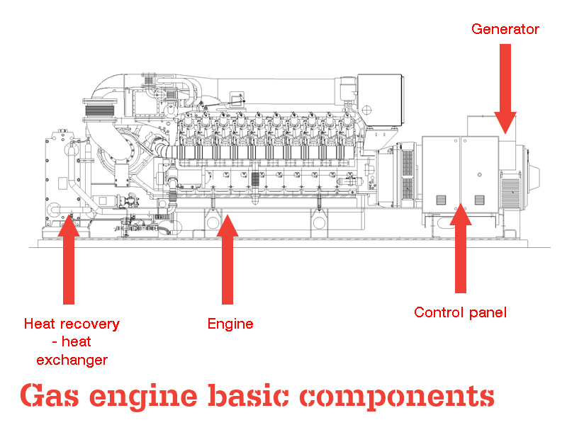
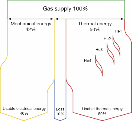
The world is experiencing steady growth. The total global&demand for energy will grow by 41% up to 2035. For over 10 years, GTL has worked tirelessly to meet the growing&demand for energy, prioritising the use of engines and fuels&which will ensure a sustainable future. GAS generator sets which are powered by environmentally&friendly fuels, such as natural gas,biogas,coal seam gas esandassociated petroleum gas.Thanks to GTL’s vertical manufacturing process, our equipmenthas proven excellence in the use of the latest technology during manufacture and the use of materials that ensure quality performance which surpasses all expectations. Gas Engine Basics The image below shows the basics of a stationary gas engine and generator used for the production of power. It consists of four main components - the engine which is fueled by different gases. Once the gas is burnt in the cylinders of the engine, the force turns a crank shaft within the engine. The crank shaft turns an alternator which results in the generation of electricity. Heat from the combustion process is released from the cylinders;This must be either recovered and used in acombined heat and power configuration or dissipated via dump radiators located close to the engine. Finally and importantly there are advanced control systems to facilitate robust performance of the generator.  Power Production GTL generator can be configured to produce: Electricity only(base-load generation) Electricity & heat(cogeneration / combined heat & power - CHP) Electricity, heat and cooling water&(tri-generation / combined heat, power & cooling -CCHP) Electricity, heat, cooling and high-grade carbon dioxide(quadgeneration) Electricity, heat and high grade carbon dioxide(greenhouse cogeneration) Gas generatorare typically applied as stationary continuous generation units;but can also operate as peaking plants & in greenhouses to meet fluctuations in local electricity demand. They can produce electricity in parallel with the local electricity grid, inisland mode operation, or for power generation in remote areas. Gas Engine Energy Balance
  Efficiency & Reliability The class-leading efficiency of up to 44.3% of GTL engines results in outstanding fuel economy and in parallel the highest levels of environmental performance. The engines have also proved to be highly reliable and durable in all types of applications, particularly when used for natural gas and biological gas applications. GTL generators are renowned for being able to constantly generate the rated output even with variable gas conditions. The lean burn combustion control system fitted on all GTL engines guarantees the correct air/fuel ratio under all operating conditions in order to minimize exhaust gas emissions whilst maintaining stable operation. GTL engines are not only renowned for being able to operate on gases with extremely low calorific value, low methane number and hence degree of knock, but also gases with a very high calorific value. Usually, gas sources vary from low calorific gas produced in steel manufacture,chemical industries,wood gas, and pyrolysis gas produced from decomposition of substances by heat (gasification),landfill gas,sewage gas, natural gas, propane and butane which have a very high calorific value. One of the most important properties regarding use of gas in an engine is the knock resistance rated according to the ‘methane number’. High knock resistance pure methane has a number of 100. In contrast to this, butane has a number of 10 and hydrogen 0 which is at the bottom of the scale and therefore has a low resistance to knocking. The high efficiency of the GTL & engines becomes particularly beneficial when used in a CHP (combined heat and power) or tri-generation application, such as district heating schemes, hospitals, universities or industrial plants. With governmental pressure mounting on companies and organizations to reduce their carbon footprint the efficiencies and energy returns from CHP and & tri-generation & installations have proven to be the energy resource of choice.